
Support
Full power for your satisfaction
Discover the answers to your questions about powerIO® as well as further instructions and technical details. If you need any further technical support, our technical support team will be happy to help you!
FAQs
The most frequent questions about powerIO®
1. How many powerIO®-boxes can be installed consecutively?
The maximum number of powerIO® boxes on a powerIO® line is 32. However, the participants can be divided by several lines in the building.
2. How long can you build a line?
The possible lengths of the powerIO® line are limited by physics. There are the following factors which have to be considered:
1. In case of a short circuit on the 230V side, the fuse must blow within a certain time. This depends on the length of thepowerIO® cable and the setting of the protective device. In technical rooms a high tripping current can be set at the motor protection switch by our 4mm². Thus, many consumers and pumps can be connected, but only short distances of usually less than 40m can be realized - in technical centers, however, usually sufficient.
2. With low settings on the safety device (e.g. 2A release current), distances of up to 200m can be realized with the 4mm² power cable. This is the right setting for room automation with low loads but long distances (fire dampers, volume flow dampers...). Thus, e.g. 2 powerIO® lines can be operated separately: One for the technical center and one for the room automation.
3. The distance between two powerIO® boxes is limited to a maximum of 100m.
3. How many participants can I connect per box?
1. A box has 4 x M12 RS485 (port 1 to 4) connections when delivered. To each of which 4 serial participants can be connected. In total there are 16 participants.
2. Additional protocols and devices can be connected to the individual slot (port 5). (Also Ethernet participants).
4. Via which protocol do I get the data of the sensors and actuators?
5. Must the variables be mapped and parameterized?
.
6. What do I do with additional protocols like M-Bus, KNX, EnOcean etc.?
Additional protocols can be connected to port 5 via our additional boards. This makes every powerIO® box highly modular. Expansion boards are available here.
7. How many consumers 230V and 24V can I connect per powerIO®-box?
There are two 230V outlets for each powerIO® -box. These are to be protected by microfuses with a maximum of 6A per outlet. The 24V power supply unit can supply a maximum of 1.9 A for the ports 1-5 in total.
8. Do I need accessories, if so which ones?
Mounting plate: There are additional mounting plates for the installation, which can be mounted in advance. Thus, the position of the powerIO® box can already be fixed on the construction site and the installation of the powerIO® line can be started. Afterwards the box is only screwed onto the mounting plate.
Bluetooth Dongle: Additionally there is a Bluetooth Dongle, which can be plugged in via port 6. With the help of the Bluetooth Dongles a connection to the powerIO® box can be manufactured.
Additional boards: Further additional boards can be connected to port 5. These allow to use other protocols.
Weather protection device: For installation outside of buildings we also offer a weather protection device.
9. Can I only connect certain device manufacturers to the powerIO®-box?
No. The devices that are connected must only speak standardized protocols such as Modbus or BACnet.
Devices that are already created in the powerIO® app can be put into operation directly. If you are using devices which are not yet created in the powerIO® app, please contact support@powerio.com directly so that we can add them.
10. What do I do with devices from manufacturers that are not available in the powerIO®-App?
If devices are missing, please contact support@powerio.com directly. We will add them as soon as possible.
11. Is the powerIO®-App absolutely necessary?
12. How do I configure the RS485 comports of the powerIO®-Box?
The best way to connect to your smartphone and the powerIO® box is via the Bluetooth dongle. With the help of the powerIO® app you can then edit the individual COM port settings. Via the web interface of the box (enter the IP address of the box in your browser) the COM port settings can also be edited.
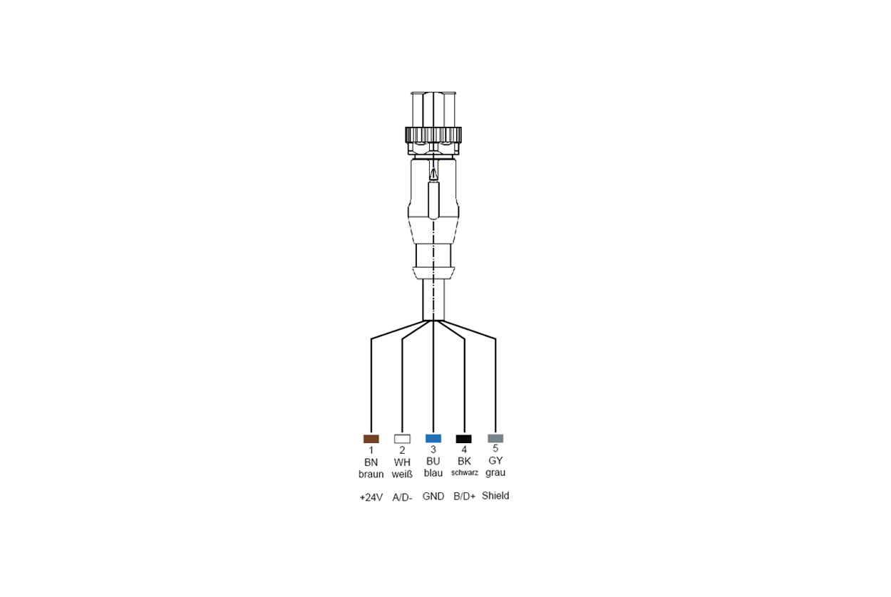
13. What is the assignment of the M12 connector?
For port 1-4
Pin
1: Brown (BN) +24V
2: White (WH) A/D-
3: Blue (BU) GND
4: Black (BK) B/D+
5: Grey (GY) shield
14. Are there planning aids, templates etc.?
There are ready-made macros for EPLAN, which are also available in the download area.
15. Which controllers can I use with the powerIO®-System and what do I have to consider? Are there ready-to-use libraries available?
For CODESYS based controllers (CODESYS Standard 3.5, Wago, Beckhoff...) there is a library for Modbus devices from leading manufacturers like SplusS, Thermokon, Oppermann, Belimo, Grundfos, Wilo, EBM-Papst, Ziehl Abegg, Rosenberg. If devices are missing please contact: support@powerio.com.
16. Why can't I wire and address the communicative participants directly serially? Why do I need the powerIO®-Box?
1. Confusing: How do you document a network of 40 or more serial participants? You don't know which device is connected to what.
2. Troubleshooting: What happens if there is an error and e.g. a device causes a bus short circuit? Finding this device is like finding a needle in a haystack.
3. Speed: If you have many participants on a serial bus and you also want to write values quickly so that actuators go on or off, e.g. for lights, then this cannot be realized. But this is possible due to our decoupling to fast TCP.
4. Multiple bus protocols: In a purely serial system, you can only use one bus protocol per data line pair. In a TCP network you can use several protocols in parallel. This means that if there should be an M-Bus meter somewhere near the next powerIO® box, you can simply include it directly.
5. Power supply: Purely serial networks are often accompanied with 24V. With 24V it is not possible to realize long distances and also larger 24V consumers like flaps, valves etc. often overload the line quickly. Consequence: A separate power supply must be installed again and again. In addition, 230V consumers have to be completely extra wired - but these are also available in technical centers and in the "field" (zones, individual room control). With the powerIO® system there is a separate 24V power supply per box as well as 2x 230V outlets which can be used directly.
17. Can I install / use powerIO®-Box outdoors?
Yes, the protection class is IP56. However, we recommend, if possible, to mount the powerIO® box inside the ventilation system, for example. If this is not possible, our optional weather protection device is recommended, because sun, water etc. cause plastic and cable to age very quickly despite UV resistance.
18. How do I integrate conventional digital / analog signals and resistance sensors?
Of course there are existing systems or devices that are not communicative (e.g. interfering contacts of devices). The goal is to realize as much as possible via communicative devices. If nevertheless classical digital and analog inputs and outputs are needed, they can be connected via the additional slot Port5. Additional boards with inputs and outputs are available. Furthermore there is the powerIO®-IO extension. This is a small box with some inputs and outputs and manual override. It can also be installed in small switch cabinets, e.g. to control old fans.
powerIO®-System
Here you can find more information about our system.
powerIO®-Products
All necessary components from one source. Click here for an overview.
powerIO®-Contact
Please contact us. We are looking forward to you!
powerIO®-Demo case
Request your free demo case here.

powerIO GmbH
Eberhardstr. 65, 70173 Stuttgart
 0711 99887200
 office@powerio.com